
The Grid-Eye from Panasonic is a low resolution thermal imaging sensor. With a frame rate of 1 - 10 fps it's not aimed at high end applications but rather where sensing thermal differences or locating objects of different thermal signatures can be done with low fidelity. With its 8x8 sensor array it produces highly pixilated images that are meant for basic detection rather than analysis.
When I first saw the Grid-Eye about a year ago I couldn't think of any real interesting or innovative use for such a sensor. However, soon after that I had an issue where the front tires on my car needed to be replaced due to uneven wear caused by suspension and alignment issues. Because wear causes heat, if the heat signature of the tires could be monitored then maybe tire due to suspension alignment related issues could be prevented by simply looking for uneven heat signatures on the tires.
Unboxing
The unboxing of these two units was rather unremarkable. Although marketed through Element14 as one kit, what was provided is clearly two separate kits that can, if desired, be used together. The MAXREFDES130# is marketed for home/building automation and other automation applications. This comes in a rather flimsy generic box, with no readily visible markings to let you know what is contained within the box, it's rather unimpressive and somewhat disappointing. The MAXREFDES131# also comes in a generic box but this one appears to be an antistatic box and more structurally sound. Unfortunately this box also is rather badly labeled with also just a small white sticker on the side with a part number. In both cases from the outside of the box one would only be able to know that a Maxim Integrated part is contained within and its part number.
The box with the MAXREFDES130 contains the MAXREFDES130 which is contained in an antistatic bag, an RJ11 cable (~54”), AC adapter (24v, 1A), 4 region specific plug adapters [Type A (North America), Type I (Australia, Argentina, China, New Zealand), Type G (UK) and Type C (Europe, South America, Asia)]. This is all then wrapped in pink foam and unceremoniously stuffed into the box.
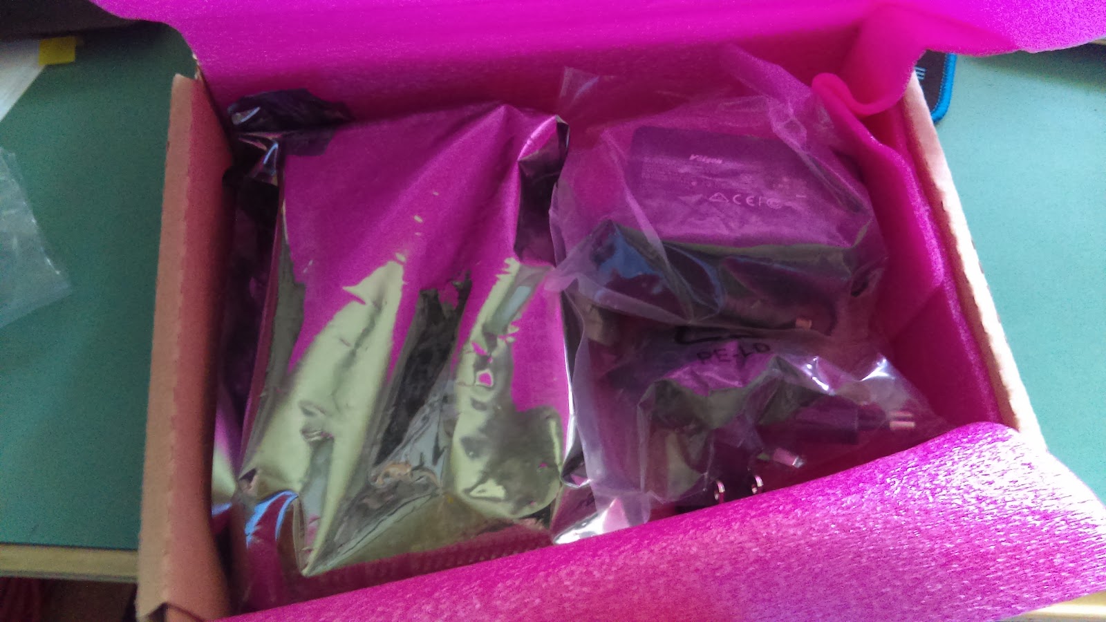
MAXREFDES130# original packaging format
The second box with the MAXREFDES130# is neater but only because of the fewer contents. The box contains the MAXREFDEs131# pushed into antistatic foam and a RJ11 cable of a slightly longer length.
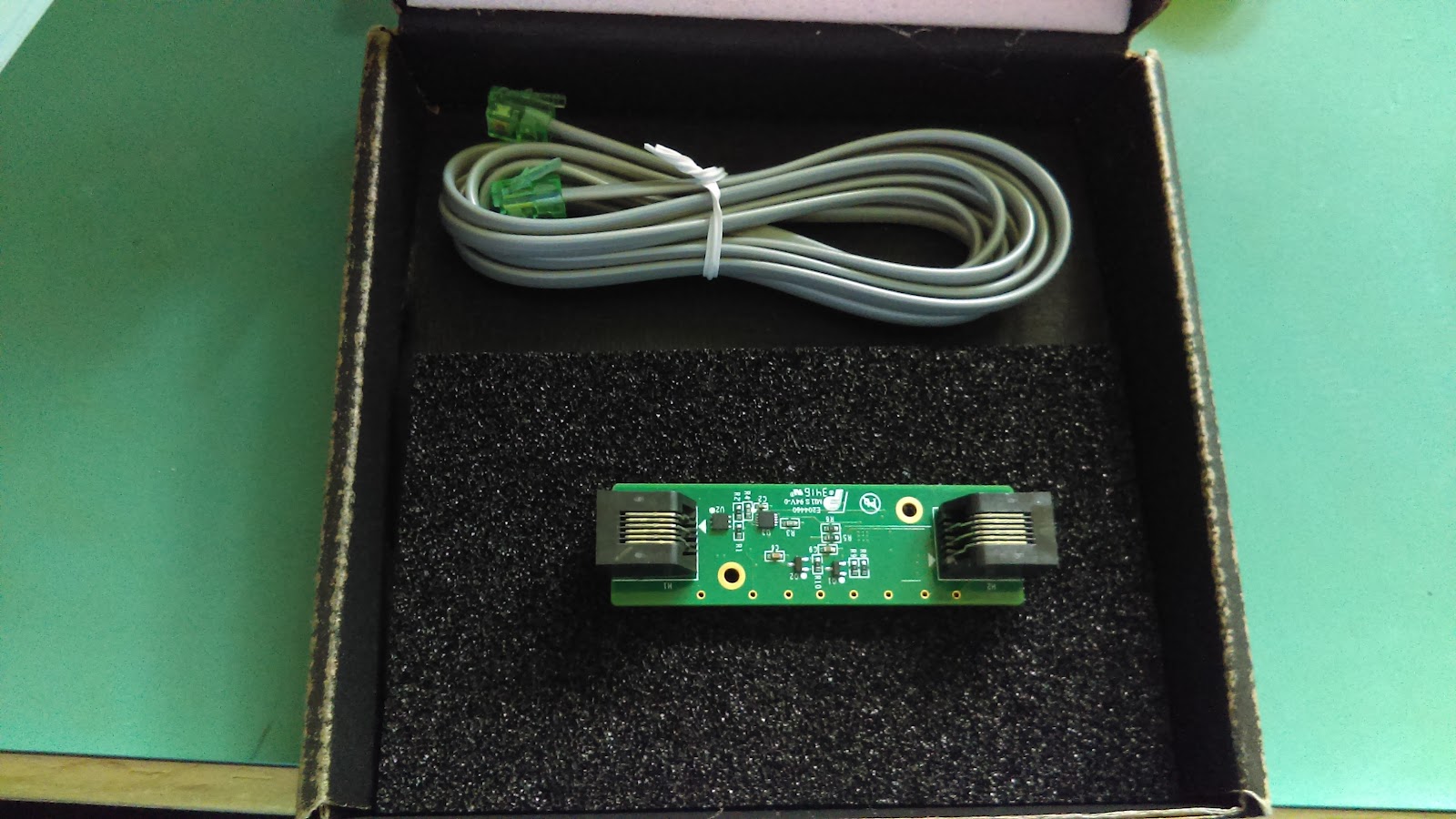
MAXREFDES131# original packaging format
Once everything was removed from the boxes and bags it was evident the feet for the MAXREFDES130# were not well tightened as a number of the feet had fallen of and where loose in the bag. While these are not critical issues it demonstrates a lack of care for a product that is supposed to show why a prospective customer should buy your product. Giving a bad impression from the start only increases the need for a bigger wow factor or better reasons later for semone to want your product over the dozens of others already out there.
Intended Uses
As mentioned I wanted to have a first hand look at this product (mainly the Grid-Eye) for its use in automotive and other more general wear and detection applications. With the cost of even low end thermal cameras costing in the hundreds of dollars and giving a resolution exceeding my needs I was curious if this could fill that space.
There were a few issues that I wanted to see if the Grid-Eye could handle. The first question is regarding the sample time of the Grid-Eye. The only value listed is for frames per second, which previously noted is between 1 - 10 fps. The importance of the sample time is that even at 10km/h the sensor would be seeing almost 3m of tire every second (~2.77m). If the sample rate is too slow then the next question is how does the sensor deal with this. Does it average over its sample time or does it take a peak value or does it just spit out garbage. Another issue and one more basic, can the sensor pick up any thermal differentials along the axial direction of the tire.
Hardware Overview
The hardware provided in these two kits differ substantially in their complexity. This very quickly becomes noticeable when you attempt to do anything that Maxim did not build into their demo software. The MAXREFDES130# contains 8 non-latching relays and 3 latching relays among many other outputs. These relays are great for turning on AC devices (10A 125V~) but with no documentation that rating is just a guess from reading the parts spec and not what the PCB might actually be designed for. The other issue is how to control them. With no manual for the MAXREFDES130# it's unclear how to control any specific part of the board.
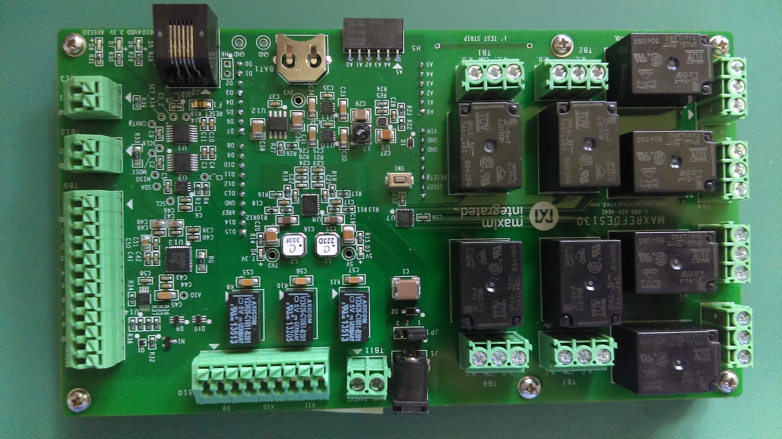
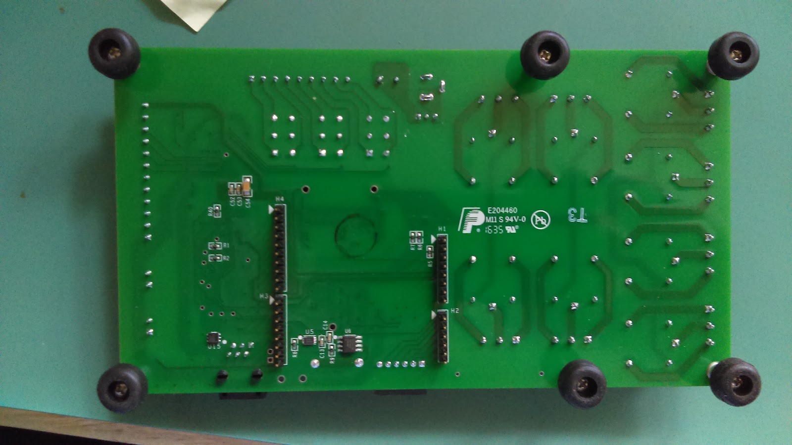
MAXREFDES130# PCB, 8 latching relays on right, 3 non-latching relays at the bottom, analog outputs on the left and 1-wire connection top left (RJ-11 connector)
This issue is unfortunately not unique to the relays. There is an RTC on the PCB as well as analog outputs but again there is no easy to follow documentation provided on how to control these components. When I brought the issue up with Maxim Integrated I was told to read all the various datasheets. With more than 9 components of various levels of complexity a short product test quickly becomes a day worth of reading. Thankfully the silkscreen does provide some pin labeling but this is the generic Arduino labels, there are still no direct links between the silkscreen labels and those connected to components. Such an example would be the SPI lines. While D1 - D15 are labeled, without referencing an Arduino document there is no clear indication what are the SPI lines. Even reading the schematic does not reveal this information.
MAXREFDES130# General control topography
All this being said, with the time invested it is possible to workout what pins connect to what control lines. It is also possible to determine the address of each I2C component from the datasheets and the schematics as well as how to control the chip select pins for the SPI devices.
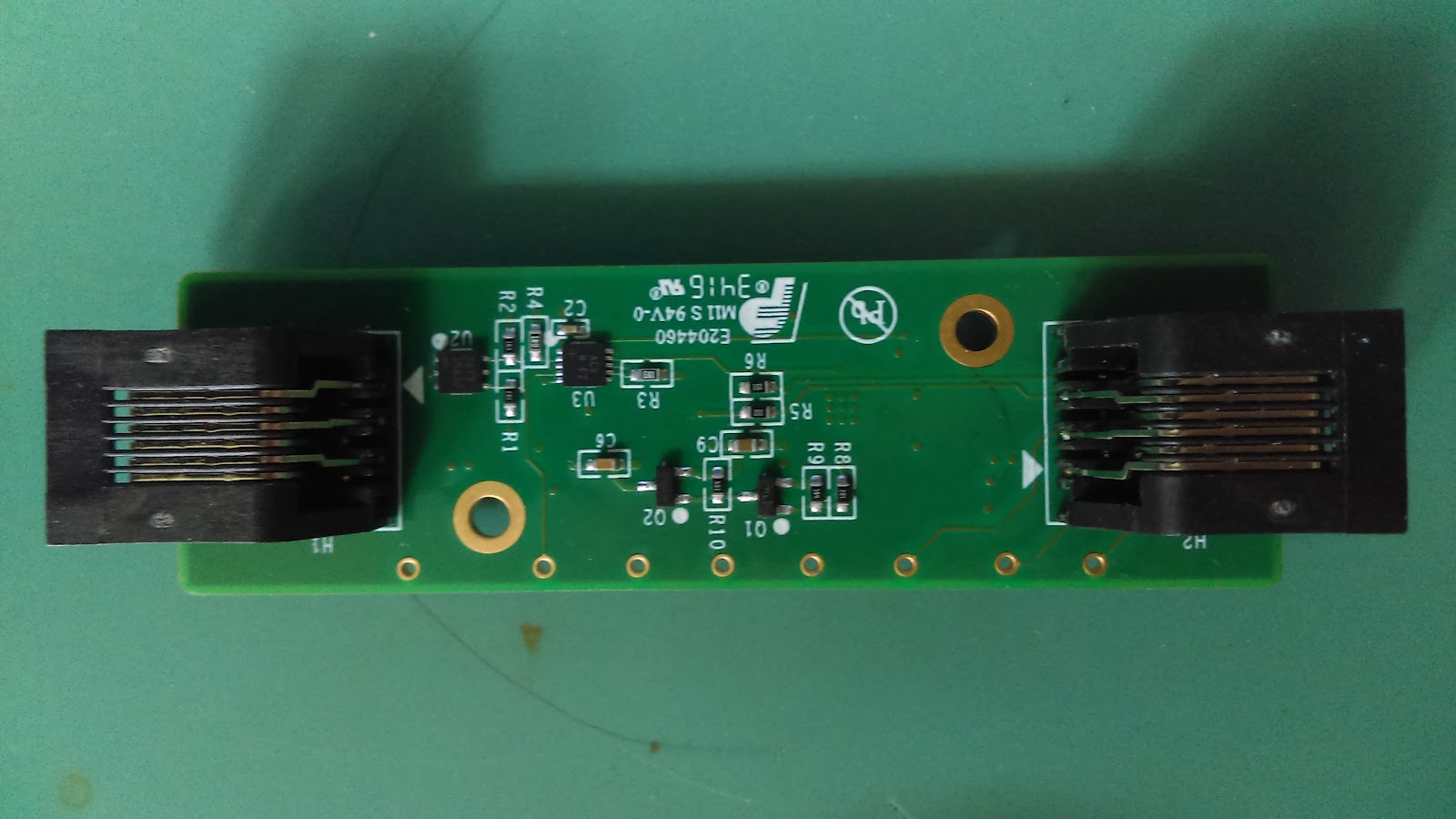
The simplicity of the MAXREFDES131# means understanding how to use the device is a lot simpler. That being said there is no marking for input and output on the 1-Wire bus. While there may be some documentation buried somewhere it was simpler to resolve this issue by trial and error. Also while the PCB is made to work with the MAXREFDES130# and therefore understandable that only the needed pins from the Grid-Eye that interface with the 1-Wire to I2C should be broken out, it would have been nice of the one or two others would also have had test points broken out.
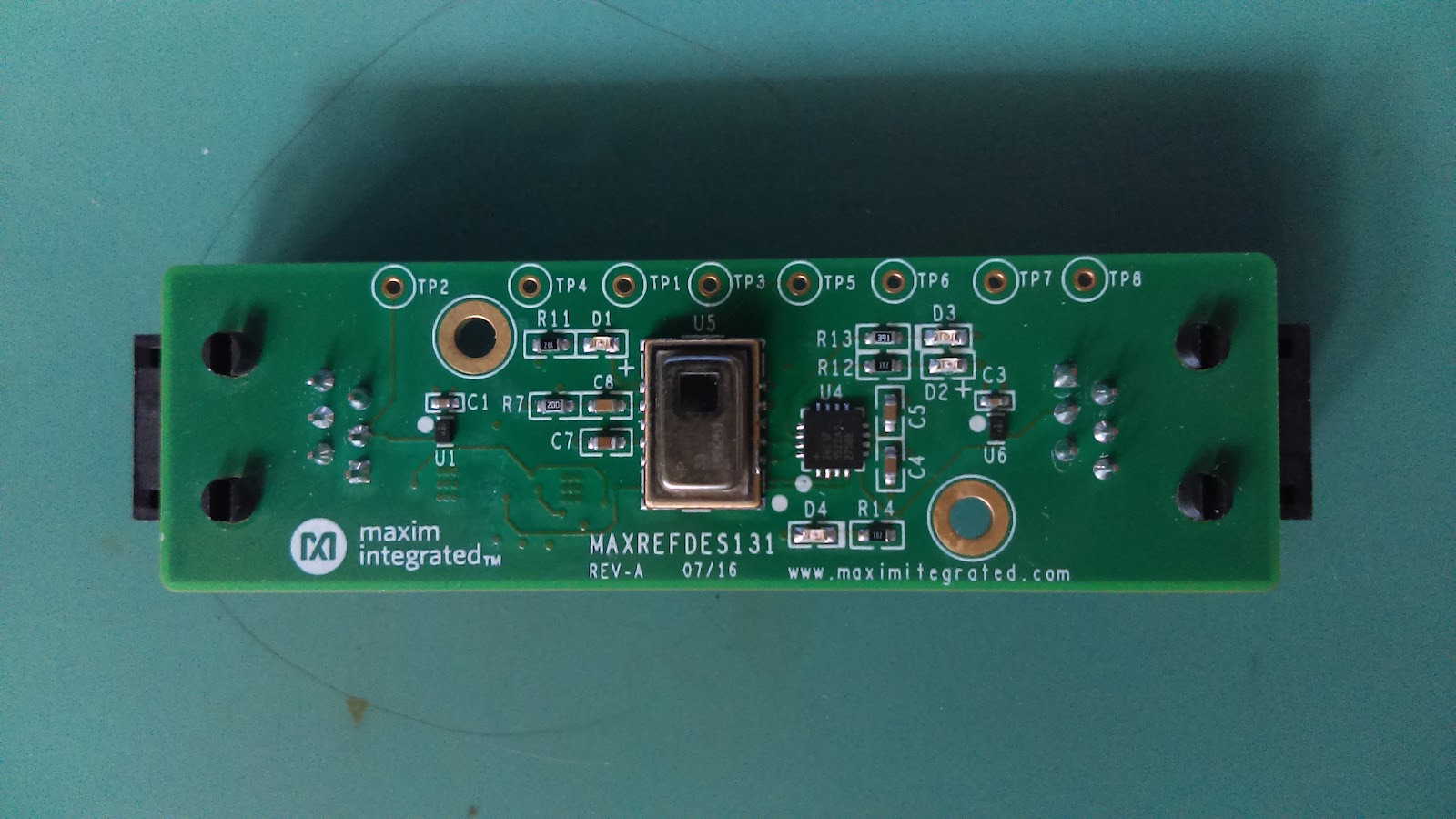
Front of the MAXREFDES131#, Test points for the 1-wire and I2C connections can be seen at the top. Input is on the left and daisy chained modules to the right
Mounting the Arduino
The MAXREFDES130# has a connector configuration that allows for an arduino to be connected to the bottom. This is very convenient as it allows for someone to quickly and easily write code for these kits ignoring the issues previously mentioned (note previous comments on software issues above).
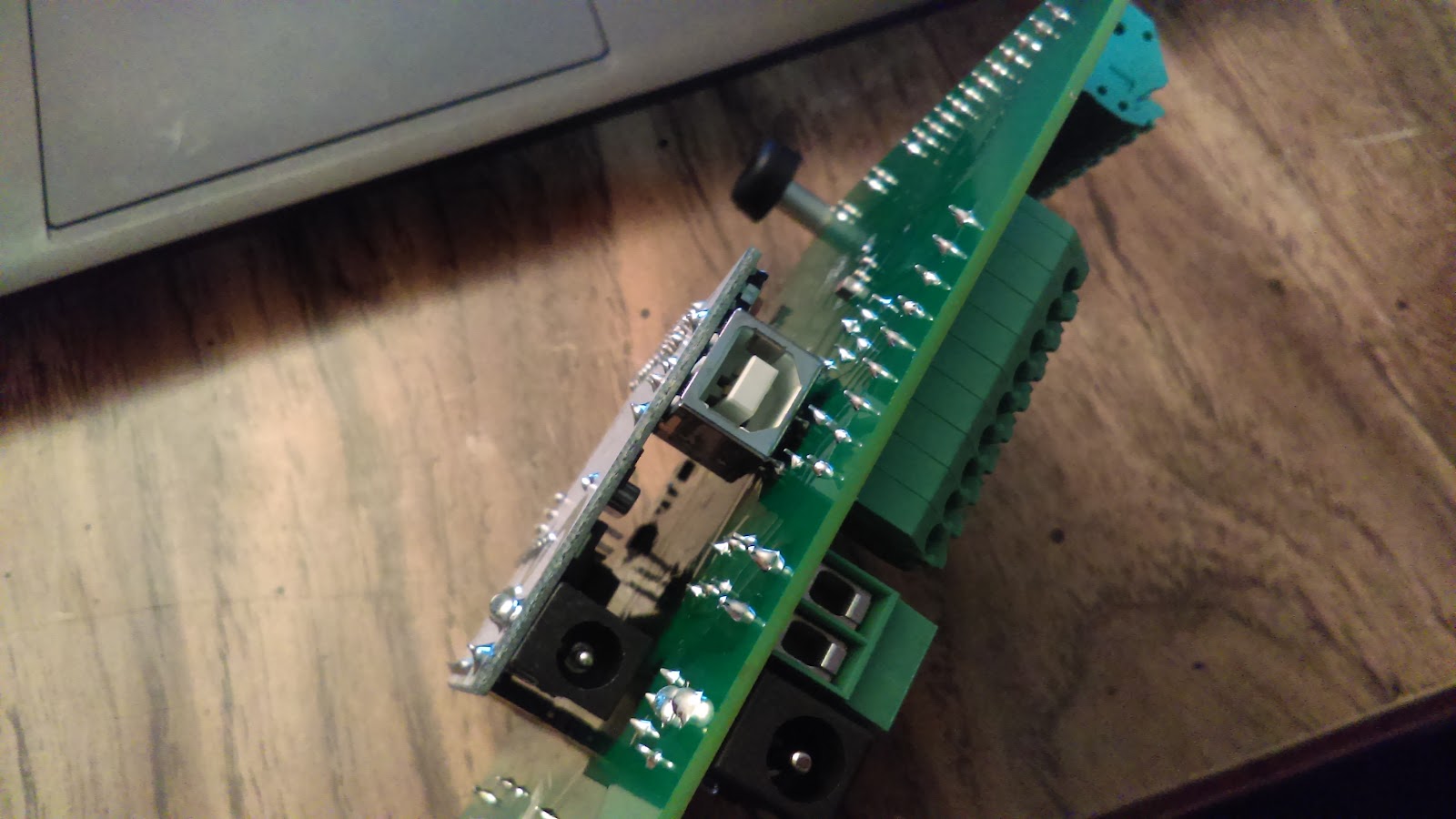
Arduino connectors at the bottom of the MAXREFDES130# with the K10 non-latching relay through hole connections above (middle set of 6 pins)
The way the MAXREFDES130# is designed to connect with an arduino has the potential to cause things to go wrong very quickly. If no care is taken four pins of the K10 relay (set, reset and the two sides of the coil) are shorted through the USB connector on the arduino . If the relay is switching higher voltages, board components can easily be destroyed.
K10 non-latching relays pins touching the USB connector on the Arduino Uno
Another point of interest that was noted during some of my testing is the required voltage to make the system operable. Even though the datasheets for the major components are listed to operate down to 4.5 V and some even down to 3.3 V the Grid-Eye will stop transmitting data if the supply voltage drops below 15.2 V and will not enumerate if the supplied voltage is below 16 V. As I was looking at automotive applications where only 12 V is available this caused some issues.
Software Overview
The demo software for a product is usually what helps a product such as this shine and reveal its true worth. Unfortunately Maxim Integrated allowed this to disappoint as well. As the MAXREFDES131# is an addition to the MAXREFDES130# the natural progression was to start with the MAXREFDES130#, unfortunately this wasn't possible. The arduino code for the MAXREFDES130# was not available and when clicking on the provided links I was instead directed to the mbed page. After I had determined that the 130# was not going to be easily doable I decided to move to the MAXREFDES131#.
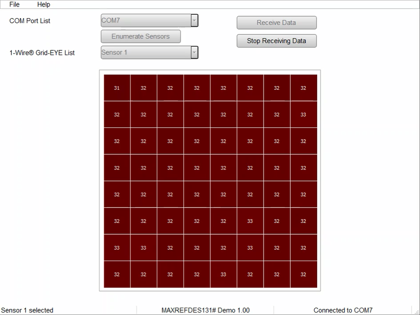
The demo for the MAXREFDES131# was much more reliable and was relatively easy to get setup. The provided software does a good job of helping you visualize the data as well as show what the sensor is sending back, even without reading any datasheets.
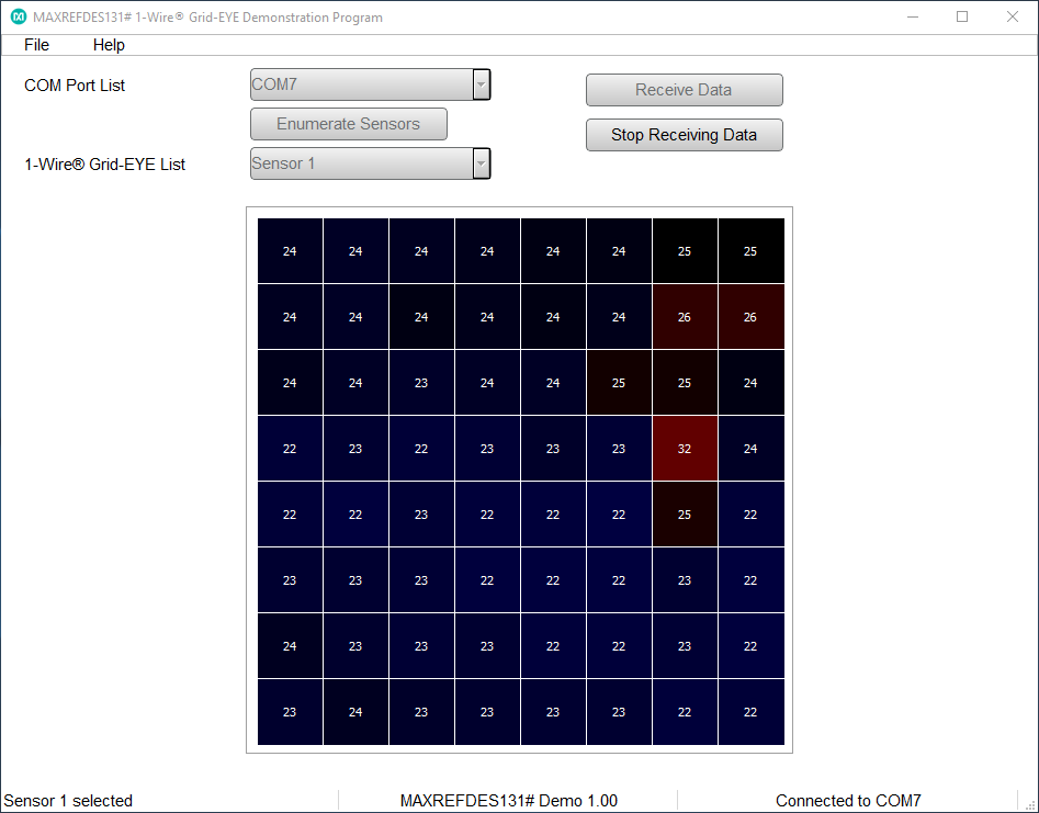
MAXREFDES131 Demo software interface
The ability within the software to daisy chain multiple sensors is also helpful. While I was not able to do so (I only have one MAXREFDES131#) its nice to know this was incorporated into the software.
Arduino vs. Energia
As someone who doesn’t use arduino often I didn’t initially have an arduino to test these kits with. However, knowing that energia is based of of the arduino framework I decided to give this a try. Installing the IDE was just as easy as installing the arduino IDE and importing the arduino project was simple.
Unfortunately when I tried to compile the project some files could not be found. Specifically the OneWire library could not be found. In an attempt to rectify this an #include directive was added to point directly to the oneWire library being used. This attempt just snowballed into adding a long list of #includes. Upon further inspection it was found most of these libraries were empty and only contained #include directives for further files which again only pointed to another level.
After attempting this for a while with not much luck, removing one error only produced more or different errors, I decided to stop. What could not be determined, that may have helped resolve the whole issue, is why energia could not find the file structure for this project. One solution that was looked at but not followed through with completely was the renaming of the oneWire library as energia already has one. It was also suggested by Shabaz that there may even be code missing that would either need need to be found or possibly the code is written specifically for the AVR and would therefore need to be rewritten or adapted for the TI parts.
Testing
As mentioned above there was a project in mind when applying to roadtest this product. But as the goal of this review is to test the functionality as well as usability of the kit a more targeted testing was attempted.
The first test after seeing how the Grid-Eye software works was to try and detect any temperature variation on my cars tire.
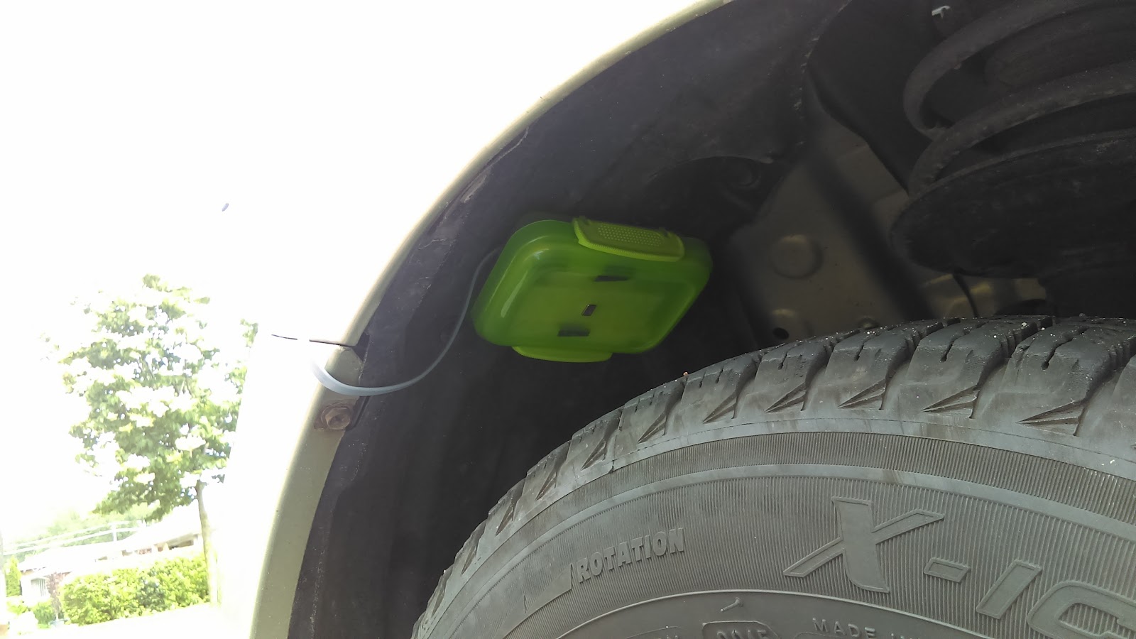
Wheel well with Grid-Eye mounted facing the outer surface of the tire
Close-up of Wheel well with Grid-Eye mounted to monitor tire temperature
While this sounded like a good place to start no variation could be detected. This was initially thought to be because my wheels are as true as could be. While this may be so there is another factor I did not take into account. The sensor has a viewing angle of 60° and with the tire ~8 cm from the sensor only 9 cm of the approximately 18 cm was being viewed (assumably nothing near the edges) so no heat differential was noticed.
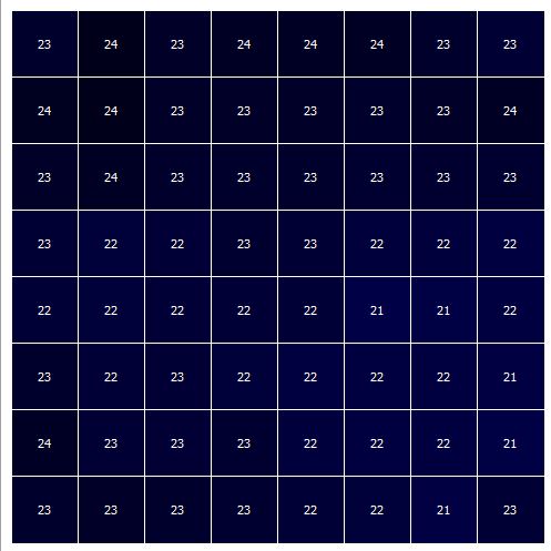
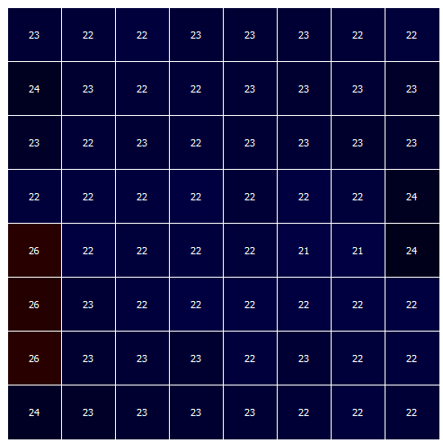
Heat signature of tire seen by Grid-Eye from a distance of ~9 cm (constant temperature)
Since the space in the wheel well is very limited I decided to verify the viewing angle. Because the only way to do this is with something of different temperature a candle was used. It was quickly determined that even though a candle is so much hotter than the surroundings it is not detectable not much further than ~30 cm from the sensor. While not 100% certain this would appear to do with averaging or sensitivity of the sensor.

Setup to test detection of candle at various distances
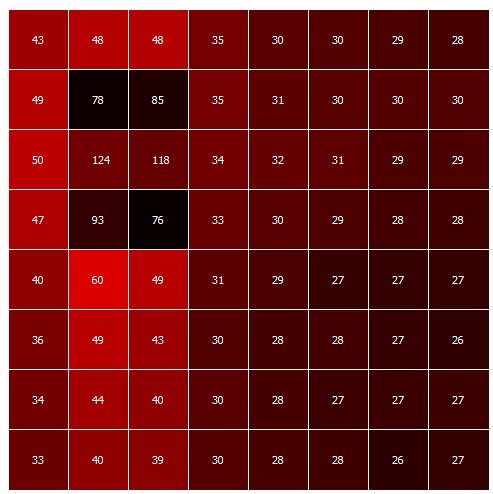
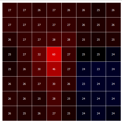
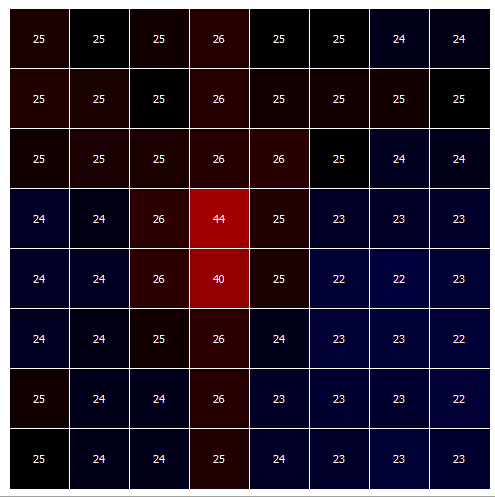
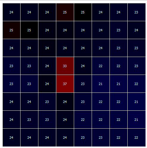
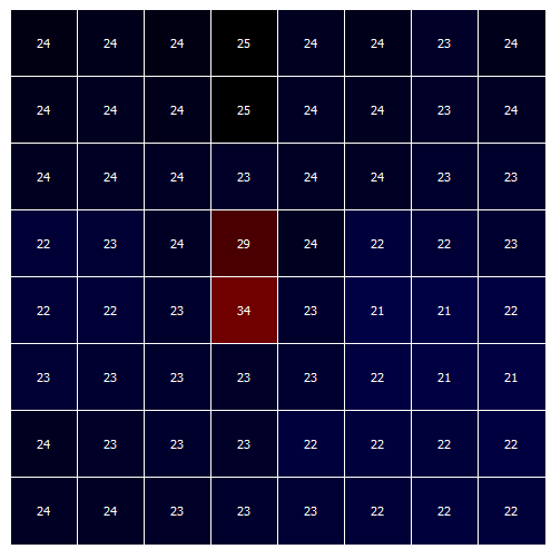
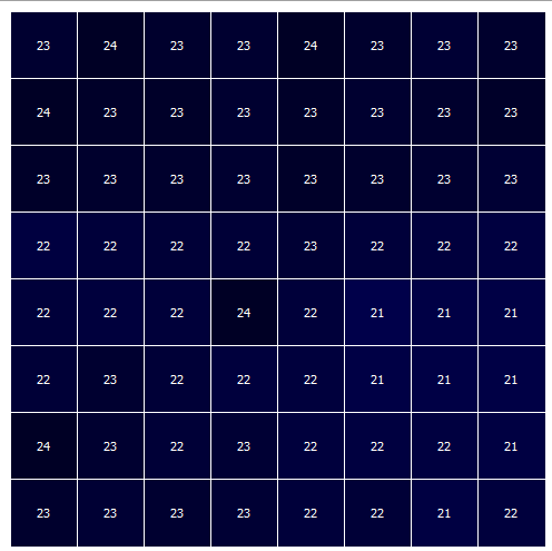
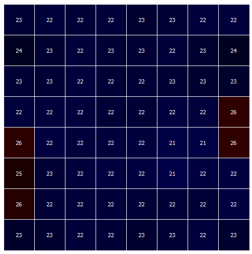
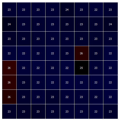
Candle at distances of 5 cm, 10 cm, 15 cm, 20 cm, 25 cm, 30 cm, 60 cm and 90 cm
Due to the unexpected result from this test and the inability to verify the viewing angle another test was proposed. This time a coffee mug would be filled with hot water and that would be used as the target. With the larger surface area the mug was able to be detected to ~150 cm, this may be larger but limited surface area prevented a larger test distance.
Once this was established to be a usable test, the viewing angle was next to be looked at.
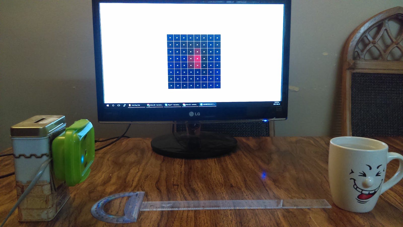
Mug with hot water test to determine viewing angle
Image Number
|
Distance from Sensor
|
Distance off Center
|
Angle off Center
|
Field of View
|
1
|
91.5
|
30
|
18°
|
36°
|
2
|
91.5
|
45
|
26°
|
52°
|
3
|
91.5
|
50
|
28°
|
56°
|
4
|
121.5
|
30
|
14°
|
28°
|
5
|
121.5
|
60
|
26°
|
52°
|


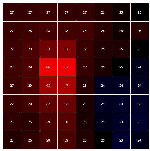
Mug placed at a distance of 91.5 cm and off center by 30, 45 and 50 cm as well as at a distance of 121.5 cm and off center by 30 and 60 cm
As can be seen from the pictures above, the viewing angle is within the prescribed specification. Although the level of detection is rather low, it would still be possible to extrapolate that there is something in that zone.
Conclusion
In after all the testing done only the Grid-Eye can really be commented on at this point. As a occupancy sensor the Grid-Eye appears to be a useful sensor as it can detect large items well however smaller items don’t show up at large distances. Based on this I would agree with Panasonic that is sensor is good for room occupancy detection as well as automation of building doors. My intended use of car tires does not look 100% feasible but with more work it may be possible. Overall it's an interesting sensor to play with and may find good applications moving forward.
No comments:
Post a Comment