Wednesday, September 24, 2014

Sending Atmospheric Data from the MSP430 and CC3100 Wi-Fi BoosterPack to Plot.ly


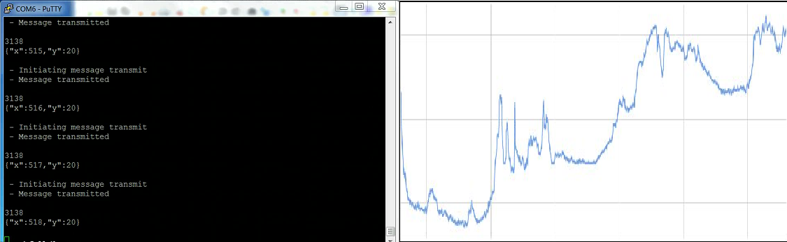
Figure 1. Terminal screen displaying live data being transmitted and demo Plot.ly graph

For a while now I have been thinking about the ability to remotely monitor what is going on environmentally in a location. I have thought about this with regards to the summer, with a cottage more than an hour away it would be nice to know what the weather pattern is for the cottages location (not the general city or county) to decide if it is worth the long drive. I have also thought about this with regards to parts of my house, such as the attic, basement etc, to help determine how well the insulation is working or what is going on in parts of the house where people may not often frequent. Lastly it has come up in many conversations with storekeepers who want to know how their fridges are performing and to know when there may be an issue. With all these usage cases I decided I should come up with a solution.

When TI came out with their CC3000 I thought I would give that a try. I spent a few weeks working with this BoosterPack in conjunction with a Stellaris (Tiva C) and MSP430G2553  launchpad but had a good few issues that just didn't seem easily resolvable as well as some limitations that hinder the usability of the system, besides by then TI had come out with the CC3100 that was supposed to resolve a lot of issues as well as be some what easier to use.
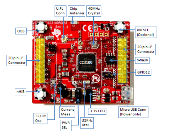
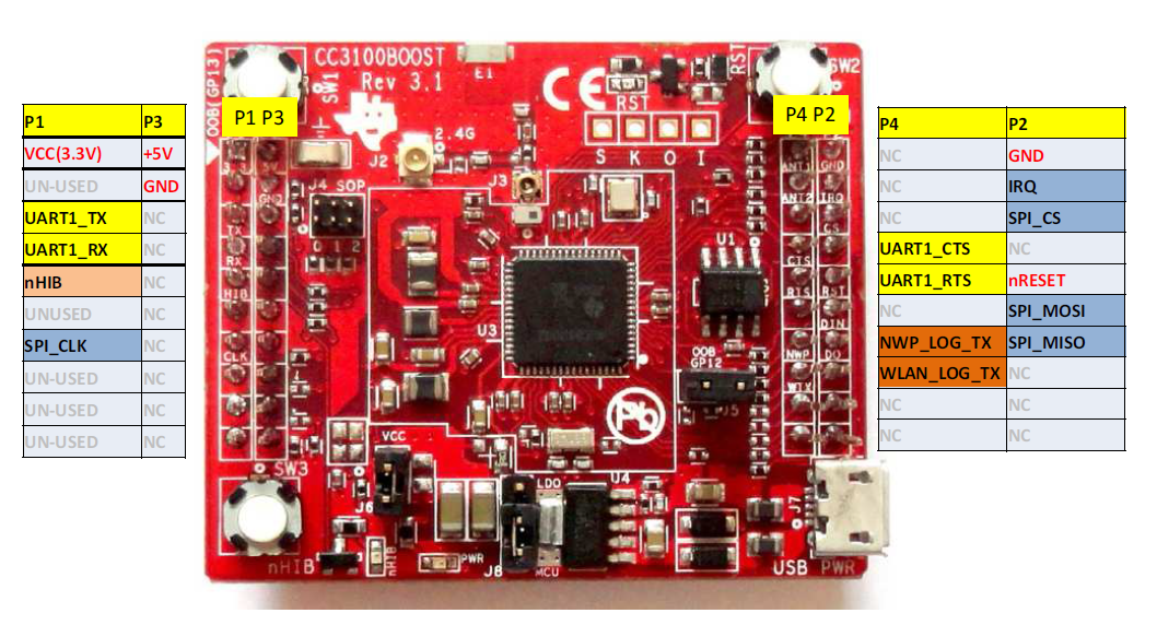
Figure 2. CC3100 layout and pin assignment

At the same time I was introduced to Plot.ly, an online graphing tool that allows for real time plotting of almost any form of data. After looking over how Plot.ly works I decided these two tools together would make a good start to resolving my real time remote data logging problem.

As I have a decent background with TI devices the use of TI products was a natural and convenient choice.The MSP430F5529LP was chosen as the brains behind the system and as previously stated the CC3100  was chosen for the Wi-Fi connection. The MSP430F5529LP was chosen do to the wide availability of example code and wide usage of this launchpad with the CC3100.
MSP-EXP430F5529LP_QSG_PinOut.png
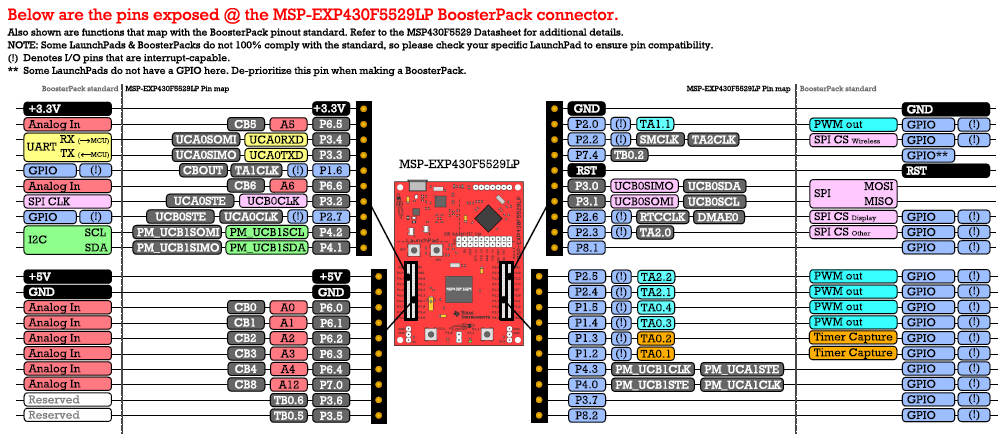
Figure 3. MSP430F5529 pin assignment for use with BoosterPacks

The Wi-Fi connection is a CC3100 Boosterpack that contains an integrated TCP stack and is interacted via SPI. One of the important features about this BoosterPack is its conformity to the BYOB (build your own board) standards.

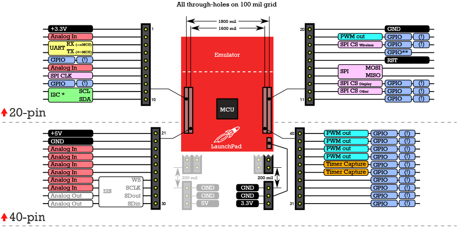
Figure 4. Build Your Own Board pin assignment layout

This means that all the pin connections are in predetermined locations allowing for ease of use with other BoosterPacks. The sensor chosen is a MPL3115A pressure sensor from Freescale and was integrated using the Xtrinsic sensor board from Element14 and Freescale. Lastly as this needs to be able to work in a remote location I decided to add a local power source, for this the Fuel Tank BoosterPack from Element14 was chosen. This choice however does present its own issue. The Fuel Tank BoosterPack does not conform to the BYOB standard. With some connections in contention this board was connected via jumper leads and for now only provides power, the power monitoring ability of the BoosterPack has not been implemented but hopefully will be in a later iteration of this project.


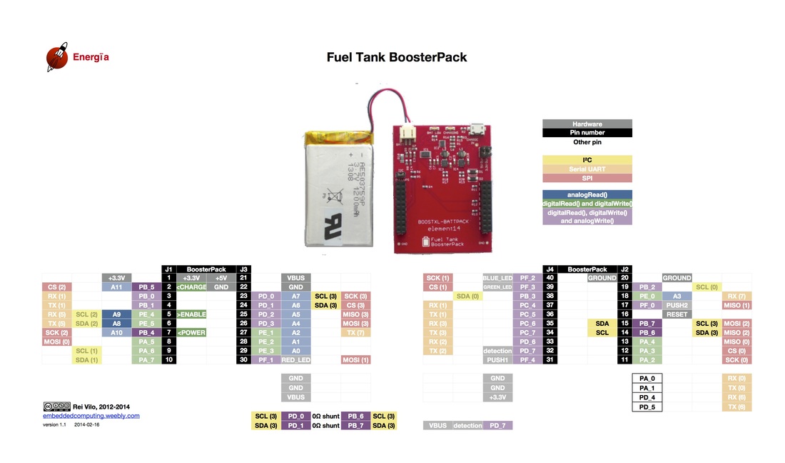
Figure 5. Fuel Tank BoosterPack pin assignment (non-conforming)


The project is based on the TCP_Socket demo for the CC3100. This demo has the basics needed to connect to an access point (AP), open a socket and send data, this provides a very substantial start for the project. This code was modified one step at a time. The first step was to allow for data of my choosing to be transmitted. This was tested and verified using a piece of software from HW-Group called Hercules. This software allows you to have a server running on your PC and to easily receive and see incoming data. One this was done the code needed to be further modified to allow for one connection to be made and multiple packets of data to be transmitted. This was done by splitting the BSDclient function into two distinct functions. The first function would take care of creating a socket and connecting to it. The second function packetTx would then take care of transmitting the desired data. Once this was done (with some difficulty, see forum posts for details), it was time to start transmitting data to Plot.ly.

The website for Plot.ly origanly did not provide a lot information if you were not using one of there standard platforms (Arduino, Matlab, etc) or one of there chosen languages (Python, R, Arduino), I therefore had to take the Arduino code (the easiest to understand) and parse it so it could be used in the format needed by the CC3100. From this code (Plotly’s Arduino code) I was able to create a graph using the REST API commands. These commands in their most basic form look like this:

POST /clientresp HTTP/1.1
Host: 107.21.214.199
User-Agent: MSP430F5529/0.5.1
Content-Length: 243
where the IP address “107.21.214.199” is the address of Plot.ly. The content length is the length of the following string in bytes that actually creates the graph (Note each line is terminated with a carriage return as well as a new line (“\r\n”)):

version=2.2&origin=plot&platform=Stellaris&un=Kas&key=ABCDEFGHI&args=[{"y": [], "x": [], "type": "scatter", "stream": {"token": "1234567890", "maxpoints": 500}}]&kwargs={"fileopt": "overwrite", "filename": "test plot", "world_readable": true}

I will explain this string briefly. Platform is the platform or language being used, from what I can tell changing this has no effect on how the graph behaves. “un” is the username, mine is Kas. “key” is your unique identifier key that allows access to your account. “args” is used to set up the individual traces, in this case I have only one trace so there is only one set of args. if you wanted more than one trace you would use something like this:

version=2.2&origin=plot&platform=MSP430F5529&un=Kas&key=ABCDEFGHI

&args=[{"y": [],"x": [],"name": "Temperature","type": "scatter", "stream": {"token": "1234567890", "maxpoints": 500},"yaxis":"y1"}, {"y": [],"x": [],"name": "Pressure","type": "scatter", "stream": {"token": "1a2b3c4d5e", "maxpoints": 500}, "yaxis": "y2"}]

&kwargs={"filename": "Temperature and Pressure", "fileopt": "overwrite", "style": {"type": "scatter"}, "layout": {"title": "Temperature and Pressure vs. Time", "xaxis": {"title": "Time (s)"}, "yaxis": {"title": "Temperature (Celsius)"}, "yaxis2": {"title": "Pressure"}}, "world_readable": true}


for a full listing of commands you can look at this documentation. “kwargs” is the settings for the overall graph such as the title, public/private access as well as others. At this point I had a graph created and was able to see it in my workspace on the Plot.ly website. I now needed to stream data, using the Arduino code for this however did not appear to help very much. I will again show the commands to open a stream and stream data and then explain them.

POST / HTTP/1.1
Host: stream.plot.ly
User-Agent: Python
Transfer-Encoding: chunked
Connection: keep-alive
plotly-streamtoken: 1234567890

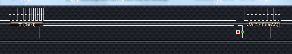
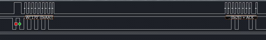
In this code the main command that you need to edit is “plotly-streamtoken”. This line is used to specify the specific trace that this data should be posted to, it is the same as the token in the args passed to create the graph. Note each line is terminated with a carriage return as well as a new line (“\r\n”). Once the stream is open data can be sent to tos graph and trace specified this is done by the following line:

3134
{"x":1,"y":5}
3134
{"x":2,"y":5}

This is where it gets confusing, the 3135 appears to be meaningless but is is infact hex for 14. There are 14 bytes transmitted here including a new line. The “X” value here can be seen to be 1, 2 and the “Y” value is 5. The order of the “X” and ”Y” does not appear to matter. Data must be transmitted once per minute or Plot.ly closes the stream, you can choose to reopen the stream (Plot.ly would prefer you don’t consttly open and close sockets) or preferably send a heartbeat (“\r\n”) if it will be longer then a minute before your next data transmission. Now that we can open a connection with Plot.ly using the CC3100, stream data to plot in reat time its time to get the data from the desired sensor.

I chose to use the MPL3115A as it is a relatively simple sensor to use and I had one laying around. The MPL3115A uses I2C to communicate and once set up to take a reading every second there is not much to do other than poll for data. This will eventually be changed to an interrupt based system which would ideally allow for the MSP430F5529LP to sleep for approximately 95% of the time (back of the envelope calculation) increasing the units life by orders of magnitude.

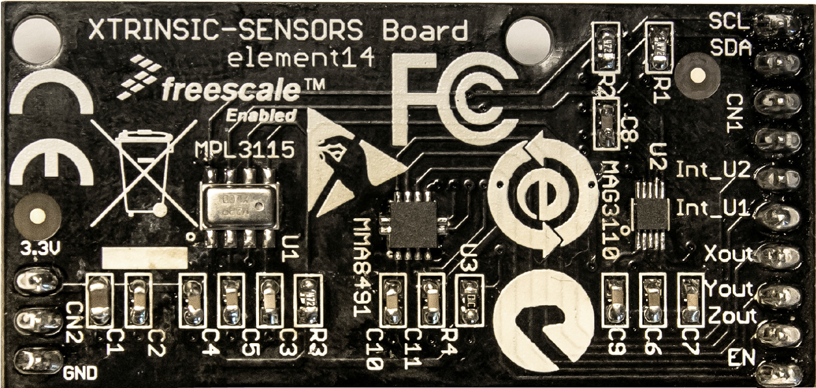
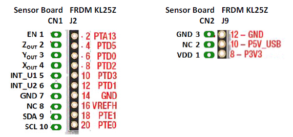
Figure 6. Xtrinsic Sensor Board and pin assignment configuration

This code was initially developed separately from the TCP_Socket code and was slowly merged allowing for issues to be easily resolved. The main issue encountered was the “Error: "Program will not fit into" after adding interrupt handler” this was eventually resolved by simply removing the interrupt handler for “USCI_B1_ISR” in board.c. Once the data is read in it needs to be changed to a string and assembeled as message that Plot.ly can interpret. This is all done in the “plotlyPlotString” function, two integers are passed in as well as a pointer to a char array. The integers are converted to chars and inserted into the string ready to be sent to Plot.ly (this function in its entierty can be confusing so if anyone would like more clarification I would be happy to further exlpain it below). One integrated and tested the system performed pretty well.

P1010197.JPGP1010203.JPG
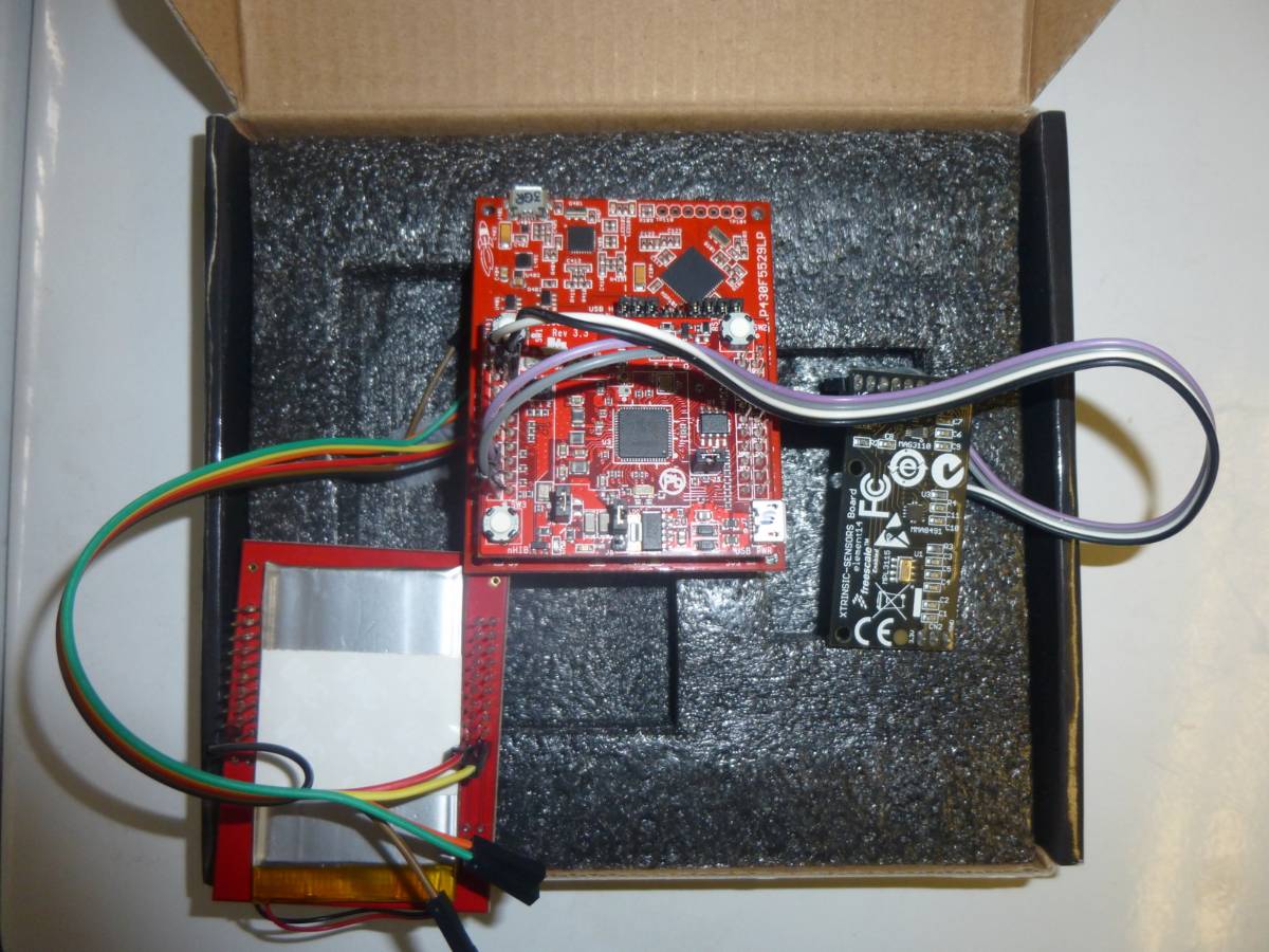
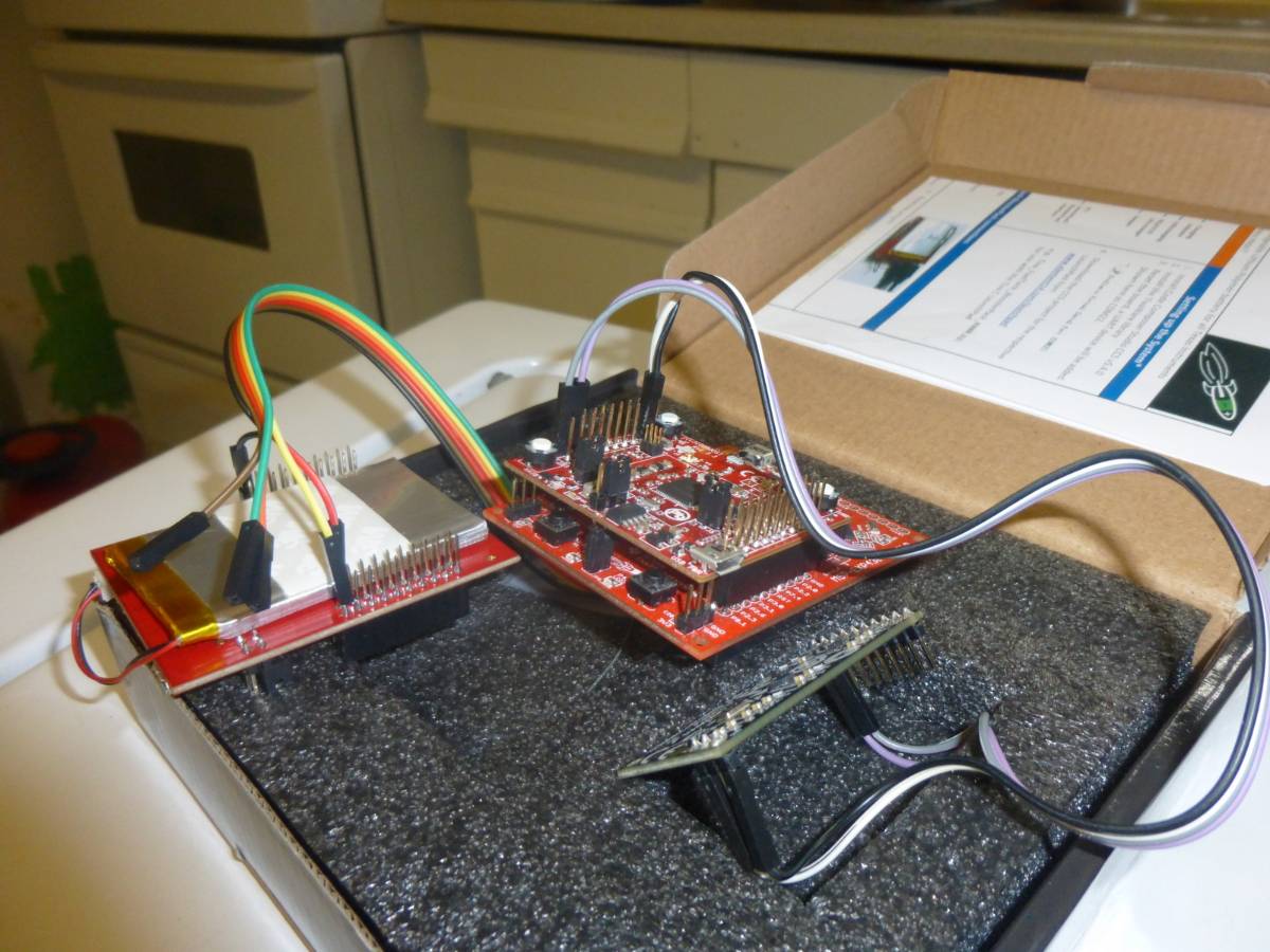
Figure 7. MSP430F5529 with CC3100 BoosterPack mounted and connected to the Xtrinsic Sensor Board (P4.1, P4.2) and Fuel Tank BoosterPack (3.3V, 5V, GND)

Next Steps
Moving forward there are a number of improvements that need to be made. As of now the system disconnects from Plot.ly after ~530 data points (this does not happen with the Hercules server), this issue will need to be resolved and is currently under further investigation. There is also the issue of inadvertent disconnections from the AP that for a robust system will need to be taken care of, this will involve checking that the connection has not been closed and if it has, to reconnect. There is also the need to check that the socket has not been closed and again if it has to reopen it before continuing to send data. Lastly for complete robutness the system should be able to check for error messages from Plot.ly and react to them in a meanigfull manour.

Besides for these steps the inclusion of pressure data on a separate “Y” axis would allow for a better use of the chosen sensor. Also the full implementation of the Fuel Tank BoosterPack with power monitoring and plotting time remaining, battery voltage and possibly other metrics would be a useful addition.

I will update this post as the project evolves. If you have any questions or comments I would be happy to address them in the comments below.

For those who would like to try this and may run into the same issues I have, I have included a link to the issues I had and how TI helped me resolve each of them

CC3100


Original post on Element14 can be found here

TI Fuel Tank BoosterPack & MSP430F5529 Launchpad - Review


Firstly I want to thank Element14 for allowing me the chance to review this  product and I must say I enjoyed the challenge a lot. This product was definitely changing and I enjoyed collaborating with both Peter Oaks (sharing tips) and Lauren Slater (getting product info). I will attempt to follow the traditional outline for a review but I ended up spending more time understanding the gas gauge and eventually the charger rather than messing around with the Boosterpack as a whole. My main goal in this review was more on the workings of the Gas Gauge and Solar Charger so comments on the actual boosterpack may be at a minimum.

Unboxing
The unboxing was exactly what I expected from a TI product (I have several of their kits). They have a clean form with no clutter and a single page to get you started quickly. There is the usual software to download but as a customer of TI and others I am used to that and expect it (nice to have the latest version before spending hours debugging)

The MSP430-F5529 has a slightly smaller box than the other Launchpads (MSP-EXP430G2, Stellaris) which is nice since it conserves a bit of space on my shelf. Inside is the usual focus on the launchpad with the cable hidden away and a message from the MSP430 team under the launchpad.


The Fuel Tank was also very nicely packed with a TI’s attention to presentation. The battery was in bubble wrap and placed firmly in hard foam to prevent it from bouncing around. The boosterpack was loose in the box. There was no USB cable for charging, thankfully there was one in the MSP430-F5529 and since that kit was not used I had a cable to spare (note to add one for future sales).

MSP430-F5529
The MSP430-F5529 requested an update when I plugged it in. This update appeared to be taking a very long time and finally freezing. Not fully thinking it through and doing the stupid thing I unplugged the board killing the EZ-FET lite programmer on board. Thankfully for the MSP-EXP430G2 that I have I was able to reprogram the programer (if you are wondering how just ask and I will lay out the steps) . After updating the EZ-FET lite again and letting it complete I was able to attempt to run some demo software on it.

I quickly realized that the code for the Fuel Tank would not run natively on the launchpad and that some fixes would be needed to get it working. After spending a good deal of time working with the Stellaris I think the MSP430Ware may resolve this issue, something I may look into at a later date. After a short period trying to get this launchpad to work with the Fuel Tank and releasing it would be some work I moved on to the board that did have code written for them.

MSP-EXP430G2
From my other projects and courses I have gone through, I have a few MSP-EXP430G2s laying around and since there is code for this launchpad and being one of the simplest boards to program I thought I would try with this next.

Unfortunately this to was going to be a project in itself. With the first few tries at compiling the code and getting odd messages (could not find files that were clearly included) I left this board alone and moved to the Stellaris instead.

I have since retired this launchpad with a bit more luck. The compiler now sees all the included files but I have 77 errors that I have elected to ignore for now and write the review without the software running on this launchpad. I am hoping once this review is complete to again attempt to get the software running on the MSP-EXP430G2.

Stellaris
The Stellaris launchpad was my third choice as I have two of these laying around at home. After downloading the TivaC Ware from TI it took a bit of coxing to get everything to compile and work correctly. On my first attempt there were issues with compiliation those were solved after reinstalling TivaC Ware. I then had issues with with getting an output from the launchpad. In that case I’m not sure if it was a baud rate issue or just a bug in the system after reprograming the launchpad a few times I was able to get the board to replay to my requests for its status information

******************************************
 This is a battery demo !    
 Press:    
 1. To see the battery main parameter    
 2. To see the battery State of charge!    
******************************************

After getting the basic operation working I wanted to look through the code to change how things worked and get some extra outputs. It was very clear that the code was NOT written by TI as they generally have comments in their code, however, in this code there were few. At times I was left guessing what the intent of the code was. I was eventually able to get done what I needed to but it took more work than it should have. I will explain more about some of these issues later.

Testing Goals
Once I had a working platform it was time to start evaluating the boosterpack. When I signed up for this road test I had a list of things I said I would test and I have done my best to get the information I said I would. This list includes:

- Reliability of its safety features
- True life of the battery
- Whether it is possible to trick the gas gauge as to how much power is remaining  in the battery - Battery life with current and voltage monitoring to check power consumption
- Low battery protection, to check battery does not go below safe charge values
- See if it is possible to change the safe charge value
- If the battery is discharged below safe values (as noted in the user manual) does the battery charge as recommended and how does this affect its overall performance and life.

During the course of using the Fuel Tank I feel I have successfully covered all of the tests I set out to perform and I will outline the results as I go through the review.

Fuel Tank
When I received the fuel tank I was excited to get started as having a reliable way to receive battery metrics for my ongoing project would be very helpful. After going through the TI Fuel Tank Boosterpack User Guide I realized this is not the usual TI documentation. Having looked through a good few of their data sheets (uC, level shifters, MUXs, etc.) I have become accustomed to documentation that is both easy to read and understand. This document may have been easy to read but following the steps was not easy. There were some steps that seemed to be missing or some that were unclear (step 3, there is no such wording in the drop down menu) and others that were just impossible (Make sure that "Copy projects into workspace" is not checked - greyed out so I could not change the selection). Having used CCS before I was able to work things out and get one working launchpad.

After getting everything started I wanted to make a connector that would easily allow me to measure voltage across the battery as well as current through from the battery. I spent some time trying to work out whose connecter they had used but to no avail. I emailed two people from Element14 and they could not lead me anywhere. Someone suggested I try JST but, although they offered help if I provided pictures (which I did), I never heard back from them.


I had a similar issue with the battery. I was looking for a data sheet to determine what the safe values were for the battery with regards to discharging and recharging. Searching for the part number on the battery turned up nothing and there was no information forthcoming on the battery either.

Reliability
For testing the battery was cycled a few times to see what data could be obtained as well as to test low battery conditions. Also tested was charging and recharging in the middle of a discharge sequence. Some interesting results about the boosterpack and possibly the gas gauge and Li-Ion Charger were obtained. I am not 100% it is the fault of the components or the design, more on this later.

Low battery protection
The first and main issue is low battery protection. I was able to get the battery down to 4% as I was hoping to a) test the recharge lockout and b) see if I could achieve a greater capacity by “reteaching” the gas gauge what low battery is. During this test however I had the output turn on when the SoC was below 10%.


While this may be annoying, it could potentially be dangerous and at the least cause irreversible damage to a battery. With this same cycle there was also no need to boost the battery (as it should per the documentation), it charged up as normal which questions either the safety circuitry for not shutting things down or the gas gauge for saying the battery was lower than it actually was. As an interesting point on a separate cycle a boost was needed when the battery was just below 10%.

Full Charge
For the charging cycle things were not much better. The battery is rated at 1200 mAh and there is an image in the documentation showing remaining capacity at 1304 mAh. I wasn't able to reach 1200 mAh nor was anyone else doing the road test. Even without this there was an issue of incorrect readings. During one charge cycle 1133 mAh was achieved but even then from 949 mAh - 1133 mAh the SoC was at 100% (see graph below).

Related to this is there is no clear definition for 100% charged. Every cycle has given me a diffrent 100% value. In the table below it can clearly be seen that although 100% should not differ too greatly (1% is ~12 mAh) there is a wide range for 100% capacity.

Test & cycle #
Charging = 100%
Stops Charging
Discharging = 99%
1/1
950 mAh
1133 mAh
1122 mAh
1/2
1074 mAh
1096 mAh
1086 mAh
1/3
1036 mAh
1060 mAh
1050 mAh
2/1
880 mAh
902 mAh
893 mAh
2/2
858 mAh
881 mAh
873 mAh
2/3
840 mAh
862 mAh
854 mAh

The graph below shows a similar result using data from test 1. After each cycle the full capacity level is progressively lower. It is also clear the large range for which the battery is considered to be at 100%.

Self Cycling
Another revelation from the above graph was the charging and discharging of the battery even when the boosterpack was left plugged in. There is no mention of such behaviour in the user guide and no apparent reason for this in the code. There may be something in the code to explain this but following the code to find this would take longer than I was willing to spend for an answer. There was a possible explanation the data sheet for the Li-Ion charger. From the brief read it appears there is switching between charging mode and load mode, presumably then during load mode the battery would discharge until a preset value, possibly 90% of full capacity. I will attempt to clarify this and comment on any findings in the comments below.
Inconsistent SoC
A possible minor issue is the reported state of charge jumping after short bursts of charging the battery. With just ~35 seconds of charging the battery jumped from 11% to 28%, this occurred on a few occasions but when looking back at the data there were some questions that made quoting that data less than 100% reliable.
It must also be mentioned that doing the math in reverse does not yield the expected full capacity. As can be seen in the graph below, the calculated full capacity is lower than any of the full capacities achieved with this battery so far. None of the calculate values are above 900 mAh but at 99% the battery is already showing 877 mAh. Unfortunately the test was stopped before achieving 100% but from previous data it can be safely assumed that the battery would have achieved well over 900 mAh.


Inconsistent Discharge Rate
The last issue on reliability that I would like to mention is the remaining mAh divided by the current rate of discharge does not equal how much time is actually left. this was witnessed by counting the ticks between the SoC being reduced by one. When the gas gauge claimed 5 mA was being drawn from the battery (could not measure this without interrupting the test) 5 mAh should be used every hour or 1 mAh approximately every 12 minutes. the reality was the SoC changed by 1 mAh after  20, 29, 27, 11 and 23 minutes. Only one of those numbers is close to the expected 12 minutes.

Wierd Issues
During the testing there were some interesting issues that came up. One was discovered by Peter Oaks when he attempted to use Energia with the launchpad and with his Arduino. The issue he had was that every command needed to be sent twice and the first reply was usually garbage. I decided to do some of my own looking into this and could not see any such behavior with the Stellaris, but there was something interesting. In the image below it can be seen that the I2C clock is being stretched almost into the next command (read command). I am wondering if this clock stretching is somehow not accounted for in the Energia code, thus requiring commands to be sent twice as the first one is ignored due to clock stretching.


Another interesting issue discovered, not really an issue but confusing, is the commands sent. In the data sheet for the gas gauge there is no commands between 0x2D and 0x34 yet in the series of commands 0x2E, 0x2F are used presumably to request remaining capacity since that is the last command issued in the code.

Undocumented command 0x2E

After looking through the bq27510.h file all commands past 0x18 appeared to be offset with no explanation, again if anything is discovered to explain this a note will be added below.

Things still to look in to
Now that the review has mostly been completed I will attempt to look into gaining full access to the gas gauge and see what setting have been set and if anything can be changed to allow for a more reliable performance. There is always the possibility that the device has not been programmed correctly and this is something I would like to look into before using this on any of my devices. TI has a eval board EV2300 that with bq Evaluation Software helps the program the bq27510-G2 correctly. Doing this may help achieve better performance from the battery or at least reveal what can be done to help the overall performance be more predictable.
Something else to look into is the possibility the bq24210 was not set correctly. There are some settings that can be adjusted on this IC that allow you to change the charge rate and possibly how far to charge it. The issue with both of these ICs is how long their data sheets are. For two very small and seemingly simple devices there is a lot to know about them to get them working correctly.
Things to mention
As I close my review there are a few things I would like to mention that may be helpful. If these suggestions were looked at perhaps the next person going through this boosterpack wouldhave an easier time putting it all together.

Firstly the user guide could do with a bit clearer instruction to help the first time user get the boosterpack working without a hitch. On the same note test your code !! I could not find anyone who got the code to run on the MSP430 with out working at it or rewriting the code.

Secondly the schematics while almost complete are hard to read. the text is fuzzy and the two components I wanted more information about had no part number, the battery and the connector.

Thirdly, document that it is possible to get data from the gas gauge even after the output is shut down as long as the launchpad is still plugged in, don't just put a cryptic message. All that is needed is a jumper to the I2C line to pull it high. This helped me in the low power stages to get some of the interesting data I got.

// If the battery capacity is too low
// We cannot read any data from bq27510
// The SDA line is always 0
// In this case, we return -1 to let main program show "charge battery"


Fourth, comment your code. this one was so frustrating because simple things took so much longer than needed just because you first needed to jump around to find what each little part did before you could understand what it is you needed.

Summery
In summary, I had a lot of fun pulling this seemingly simple board apart. It is a great extension to the launchpad series as it allows users to break free from the USB cable. YES, I am saying this is a nifty little board even with all the issues listed above. For critical systems like the rocket project I am working on, these issues can be of concern (but can be worked around) but for the most other projects this can be a great addition. I hope to keep looking into these devices as I feel they could offer a lot of potential to future projects I would like to work on, but I will need a better understanding of them first.


Original post on Element14 can be found here